by Tiwari Academy Team
NCERT Solutions for Class 7 Computer Science Chapter 6 Algorithm and Flowchart updated for new academic session CBSE and State board 2026-27. Student of grade 7 Computer will learn here about the flowchart and algorithm making during programming.
Class 7 Computer Science Chapter 6 Algorithm and Flowchart
PROCESS OF DOING HOME WORK
- Open the school bag
- Take out your school diary
- See the time table
- Take out required books and exercise books
- Do the home work accordingly
- Keep them in the bag after finishing the home work
- Close the bag.
PROCESS TO FIND THE SUM
Take first number
Take second number
Add the two numbers
Get a sum.
Similarly, to solve any problem on a computer, we analyze and understand the nature of the problem first. When we write the work involved in doing a step-by-step process, it is called an Algorithm. An Algorithm is defined as a formal set of instructions. It is a step-by-step process. In computing, an algorithm is a set of instructions. When different sets of instructions are put together, they form a computer program.
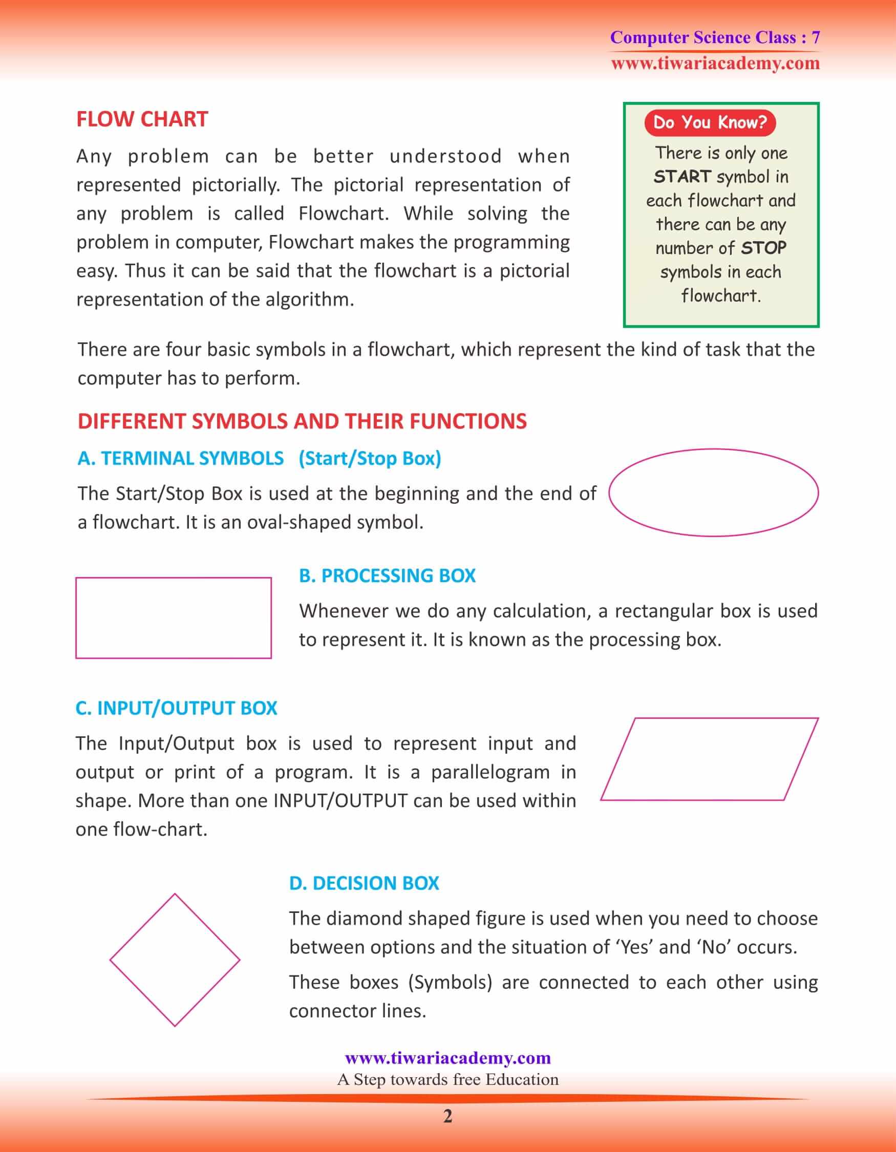
FLOW CHART
Any problem can be better understood when represented pictorially. The pictorial representation of any problem is called Flowchart. While solving the problem in computer, Flowchart makes the programming easy. Thus it can be said that the flowchart is a pictorial representation of the algorithm.
There are four basic symbols in a flowchart, which represent the kind of task that the computer has to perform.
DIFFERENT SYMBOLS AND THEIR FUNCTIONS
TERMINAL SYMBOLS (Start/Stop Box)
The Start/Stop Box is used at the beginning and the end of a flowchart. It is an oval-shaped symbol.
PROCESSING BOX
Whenever we do any calculation, a rectangular box is used to represent it. It is known as the processing box.
INPUT/OUTPUT BOX
The Input/Output box is used to represent input and output or print of a program. It is a parallelogram in shape. More than one INPUT/OUTPUT can be used within one flow-chart.
DECISION BOX
The diamond shaped figure is used when you need to choose between options and the situation of ‘Yes’ and ‘No’ occurs. These boxes (Symbols) are connected to each other using connector lines.
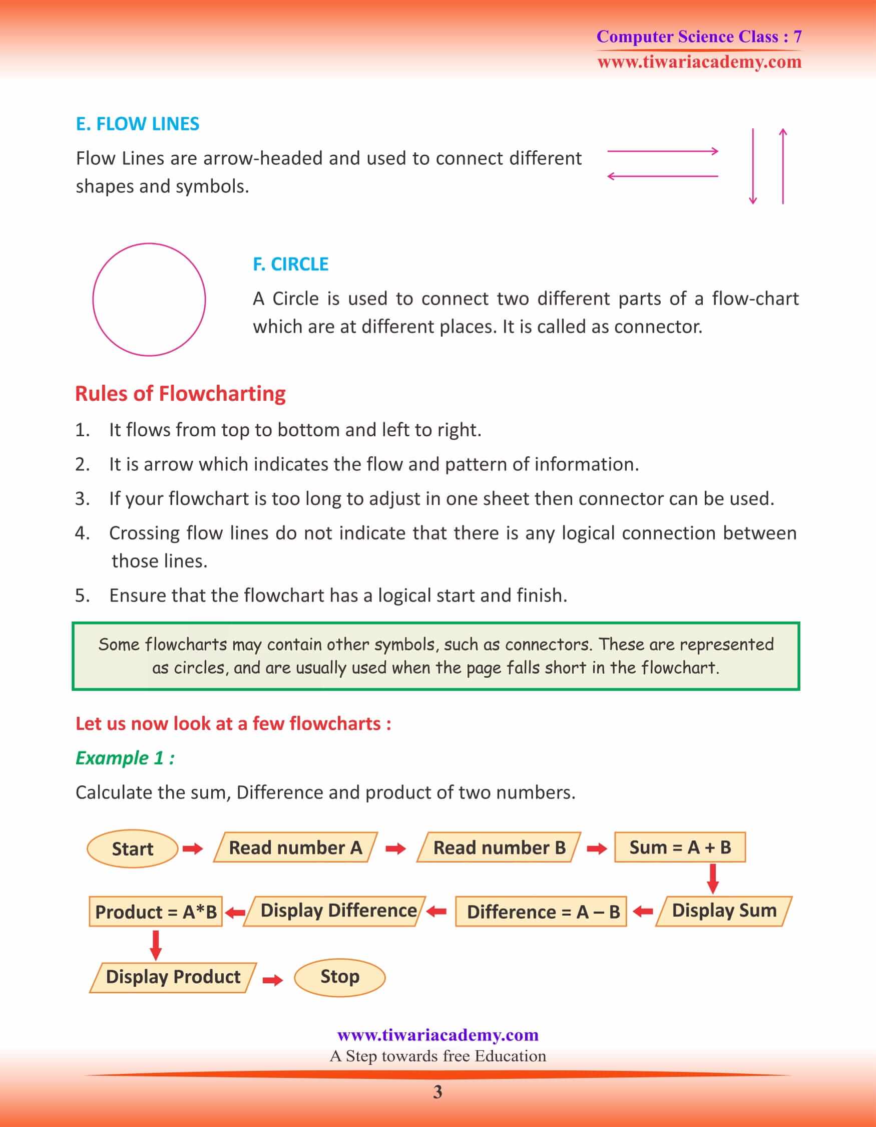
FLOW LINES
Flow Lines are arrow-headed and used to connect different shapes and symbols.
CIRCLE
A Circle is used to connect two different parts of a flow-chart which are at different places. It is called as connector.
Rules of Flow charting
- It flows from top to bottom and left to right.
- It is arrow which indicates the flow and pattern of information.
- If your flowchart is too long to adjust in one sheet then connector can be used.
- Crossing flow lines do not indicate that there is any logical connection between those lines.
- Ensure that the flowchart has a logical start and finish.
There is only one START symbol in each flowchart and there can be any number of STOP symbols in each flowchart.
The first flowchart was drawn by Frank Gilbreth in the year 1921.
Algorithm means a precise rule (or a set of rules) specifying how to solve some problem.